
mining operation ladder digram
HVAC Diagram | Standard Heating Air Conditioning
Our HVAC Diagram helps you understand the different components of your residential heating and cooling system. Learn from the experts at Standard Heating about HVAC installation!
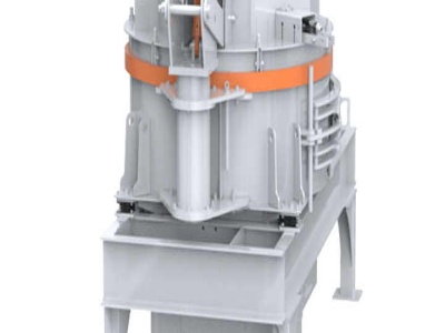
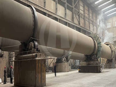
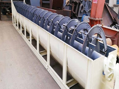
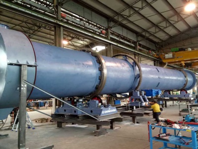
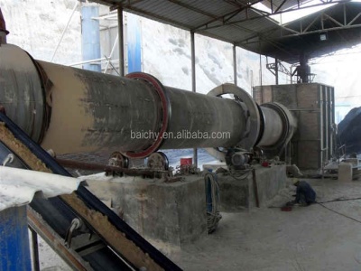
An Introduction To Surface Mining
Mining is merely defined as digging in the ground to find something of use. The process has been a part of life since antiquity, and is still the backbone of the world's commerce and production. Mining could be classified in two forms: mining at the earth's surface (surface mining) and mining underground (subsurface mining).
The Basics of Corporate Structure Investopedia
Chief Operations Officer (COO) – Responsible for the corporation's operations, the COO looks after issues related to marketing, sales, production and personnel. Often more handson than the CEO ...

To study the different industrial applications of PLC ...
To study the different industrial applications of PLC through ladder diagrams . A dissertation submitted ... Operation of PLC 1116 1213 1315 16 7. Chapter3 Programming languages Ladder language Boolean language Grafcet 1720
wiring What's a schematic (compared to other diagrams ...
begingroup Actually, JYelton's images were more consistent in circuit complexity that yours are. His had about the same number and size of ICs and many fewer discretes on the wiring diagram. While yours are the same visual complexity as each other, but the block diagram has much MUCH more complexity, and the schematic has a lot more circuitry documented than the remaining ones.


Introductory PLC Programming/Introduction Wikibooks ...
Ladder Logic. Ladder logic is the main programming method used for PLCs. As mentioned before, ladder logic has been developed to mimic relay logic. The decision to use the relay logic diagrams was a strategic one. By selecting ladder logic as the main programming method, the amount of retraining needed for engineers and tradespeople was greatly ...
Portable Ladder Safety Inspection, Use and Maintenance
Inspection, Use and Maintenance Inspection of Ladder. Ladders need to be inspected by a qualified person for visible defects before each use. While in use, a ladder may go through conditions that may impact its integrity.
Basic PLC Progrmming Universiti Malaysia Pahang
Basic PLC Progrmming. Outline Introduction to Programming Software Ladder Diagram ... Derived form relay logic diagrams Primitive Logic Operations OR AND NOT. Ladder Diagram. Ladder Diagram ... Ladder logic diagrams can be read by the programming console For this reason, ladder diagrams need to be converted into ...
Logix 5000 Controllers Ladder Diagram Programming Manual
Logix 5000 Controllers Ladder Diagram . 1756 ControlLogix, 1756 GuardLogix, 1769 CompactLogix, 1769 Compact GuardLogix, 789 SoftLogix, ... Read this document and the documents listed in the additional resources section about installation, configuration, and operation of this equipment before you install, configure, operate, or maintain this ...
1 Basic Principles of Mike Holt Enterprises
Basic Principles of Motor Controls Unit 1 (1) Ladder Diagrams (Figure 1–4) Ladder diagrams are also called "line diagrams" or "elementary diagrams." They're used to represent the function of the control circuit and the associated devices, but don't show the components of the con
What is the difference between PNP and NPN when describing ...
What is the difference between PNP and NPN when describing 3 wire connection of a sensor? Products. ... stable and efficient rail operations with EcoStruxure. Learn more. Explore more. Internet of Things. ... identify the type of sensor to be used with the PLC card based on the PLC manufacturer's documentation and / or wiring diagrams.
Technical Guide for PLC Basic Omron
1 CSM_PLC Basic_TG_E_1_1 Technical Guide for PLC Basic Introduction This guide will describe the terminology needed for basic operati on of the SYSMAC PLC .
Ladder diagram for speed control of dc motor
Ladder diagram for speed control of dc motor Products. As a leading global manufacturer of crushing, grinding and mining equipments, we offer advanced, reasonable solutions for any sizereduction requirements including, Ladder diagram for speed control of dc motor, quarry, aggregate, and different kinds of minerals.
Designing a Ladder Diagram WiscOnline OER
Designing a Ladder Diagram By Terry Bartelt. In this animated object, learners examine the design of a ladder circuit that provides manual control to a water pumping system.
15. LADDER LOGIC FUNCTIONS Educypedia
15. LADDER LOGIC FUNCTIONS INTRODUCTION Ladder logic input contacts and output coils allow simple logical decisions. Functions extend basic ladder logic to allow other types of control. For example, the addition of timers and counters allowed event based control. A longer list of functions is shown in Figure 201. Combinatorial Logic
Ladder Logic Examples and PLC Programming Examples
Jun 27, 2015· Ladder Diagram for Motor Control. Motor control can be done with a PLC program. In fact, the PLC is a common choice for controlling AC motors. Here are some examples of ladder diagrams for motor control. Star Delta PLC Ladder Diagram. One of the most common ways to start an AC motor is by first starting the motor in star connection.